Aerofoils and Lift
I thought I’d try an write something on lift. I know it’s been done to death elsewhere but I tend to find most of the ‘explanations’ somewhat lacking. They’re either pushing one particular ‘theory’ and are therefore biased or are so technical it doesn’t really explain anything. As usual I’m doing this for my own use but if by chance anyone else reads it and spots something that is confusing or just plain wrong then I hope they email me to explain the error of my ways.
Lift is the force acting on an aeroplane (in normal, straight and level flight) counteracting the downward pull of gravity. This lift is usually and/or mostly provided by the wings - but there are more advanced machines where the shape of the body provides most/all of the lifting force. Of course, if the aeroplane is in a banked turn this force also provides the centripetal force that moves the machine in a curve and in a vertical dive the lift is actually acting normal to the force due to gravity. Also, bear in mind that the tail plane of a conventional aeroplane is actually providing 'lift' in a downward direction to counterbalance the nose-down turning effect of the weight of the engine up front. So, I suppose, more generally, lift is a force generated by a wing and acting normal to the wing.
Now, the actual, rigorous mathematics of lift generation is quite complex and often done these days by computers running sophisticated computational fluid dynamics (CFD) code. All pretty unfathomable unless you are a mathematician or aeronautical engineer and to explain phenomenon such as 'wing-tip vortices' and 'ground effect' I think you really need to go into things in this kind of depth.
But there are two, well established hand waving 'explanations' out there which are much repeated even by reputable texts.
Unfortunately, one of these leads to a nasty flaw in 'understanding' and the other is, well, a horrible simplification.
Newton
The explanation involves the observation that a wing deflects air downwards. As the air was stationary before the passage of the wing and is moving downwards after it passes, it must have experienced a downwards acceleration and by Newton's 2nd law (F=ma) have had a force applied to it. This force must have been applied by the wing and, by Newton's 3rd law (for every action there is an equal and opposite reaction) the wing must experience an equal and opposite force upwards - in other words a 'lift' force.
Now there are loads of excellent photographs showing that a wing does indeed deflect air downwards (and just looking at the downwash under a helicopter's rotors should persuade anyone that it does happen).
Bernoulli
So now to the 'Bernoulli' explanation, which in its normal, simplified form is just not correct, if not plain wrong, and I want to address this here and now. Daniel Bernoulli was an 18th century scientist who did great work in fluid dynamics. Paraphrasing his principle horribly, it states that if an element of a fluid goes faster, its pressure drops (I'll do a much simplified 'proof' of a simplification of this later on). So, the simple Bernoulli explanation of lift goes like this:
Aeroplane wings (aerofoils) are curved on top and flat(ish) on the bottom. So, as the air flows past it, the air on the top has to travel faster than that on the bottom to get to the trailing edge with the bottom flow of air and therefore the pressure on the top of the wing will be less that that on the bottom and so there will be a net lifting force - QED.
Superficially this looks really quite good BUT if you look at it more carefully you can spot any number of flaws such as:
• Why does the flow over the top have to meet up with the flow it's split from on the bottom and therefore have to speed up at all? In fact, it doesn't and the air over the top actually gets to the trailing edge way before the flow on the bottom - quite counterintuitive.
• A sail on a yacht produces lift, The wind produces a nice curve in the sail - but the path length along the top (convex) surface of the sail is pretty much the same as that along the bottom (concave) surface. Same for a single surface hangglider - which I can attest to by dint of personal experience really does fly.
• How does a flat-winged paper aeroplane fly then?
• How can an aeroplane fly upside down when the curved surface is below the flat one?
• To be factually correct, Bernoulli's equations actually only apply along a streamline (the path an element of a fluid travels along). So comparing the streamlines below a wing and those above really doesn't say anything about relative pressure changes between them. Ok, you could make allowances for this but not simplistically as this explanation does.
… and so on.
If you still don't believe me let's do some simple calculations based on a Vans RV4 kit plane. This has a wing which is about 7m in span, 1.5m in chord (front to back) and its thickness is about 15% of the chord (say .225m). Now let's simplify the aerofoil to just be a 'segment' of a circle (area bound by a chord and the intercepted arc. I know this isn't exactly the same as an aerofoil but seeing as the Bernoulli explanation is just about path differences our calculations should still be in the same ball-park.
The figure below shows what I mean. Lets do some sums …
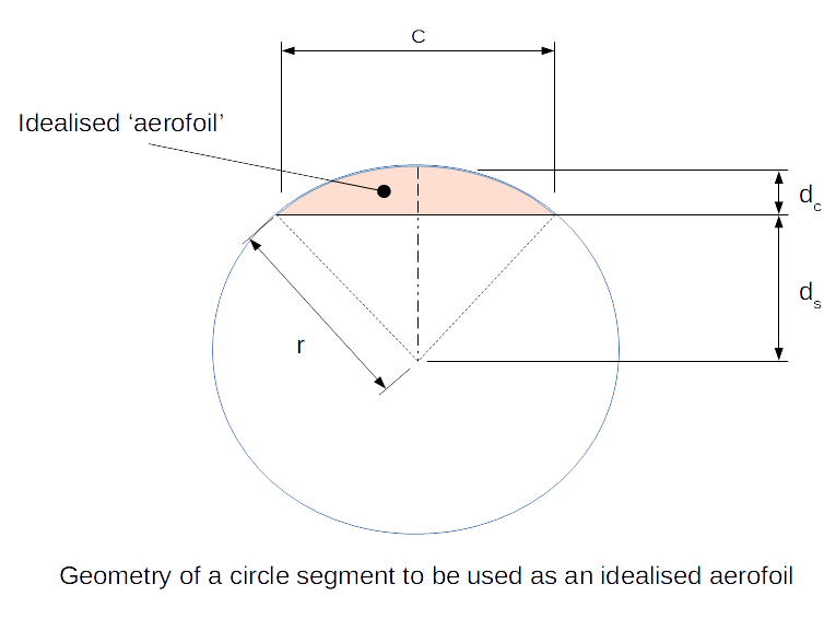
The geometry of this gives us:
$$ C = 2rsin({\theta} / {2}) = 2 \sqrt{r^2 - d_s^2} \tag{1}$$
using
$$ d_c + d_s = r \tag{2}$$
and rearranging we get
$$ d_c = r(1-\sqrt{1-sin^2 (\theta/2)}) \tag{3}$$
Finally dividing equations 1 and 3 we can get
$$ {C/d_c} = {{2 sin(\theta/2)} \over {1- \sqrt{1-sin^2(\theta/2)}}} \tag{4}$$
which can be simplified to
$$ {C/d_c} = {{2 sin (\theta/2)} \over {1 - cos(\theta/2)}} \tag{5}$$
Also (angles in radians) the arc length of the segement (alos) is given as,
$$ alos = 2 \pi r {\theta/2 \pi} = r \theta \tag{6}$$
Now, for the RV data given it is possible to use these equations to calculate the arc length for a chord length (C) of 1.5m which gives us the upper surface length for our model aerofoil. I used a spreadsheet 'goal seek' and equation 1 to first find a \(\theta\) matching the \(C/d_c\) (1.5/0.225) value, then r from equation 2 and finally arc length from equation 6. This gives an arc length of 1.5884m so arc length/chord of 1.059. This is the ratio of upper surface to lower surface distance of our aerofoil and therefore (according to the simplified Bernoulli lift hypothesis) the ratio of fluid velocity over the wing to that below it. Hmmm... doesn't seem a lot does it? Can that really produce 850kg wt of lift?